Roland
Justin approached me with a special project, flying a dummy for a movie premiere. He had in mind something like the Proto Reflex, which would be totally encased within the dummy so it would look super slick with no props showing. The Reflex is indeed an impressive bit of engineering, but to me it seemed way too complex and expensive for this application. I started brainstorming and became convinced that I could make something much simpler.
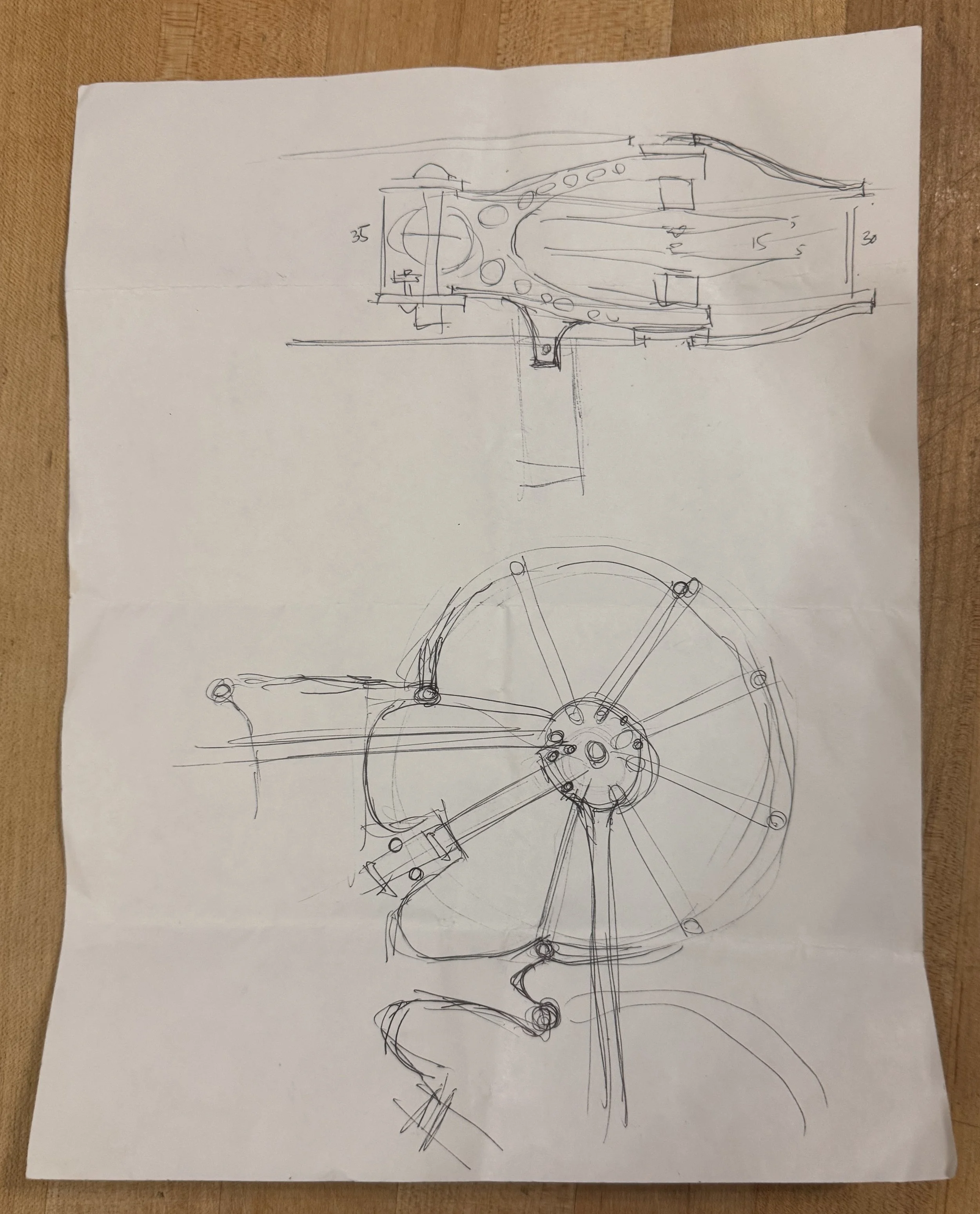
Unfortunately I left for vacation the very next day, so I spent the next few days sitting in Parisian cafés ignoring my wife and daughter, staring off into space and mentally designing the frame. After about three days I drew it up.
The idea is to use Siccario-style sandwiched arms. I added a little tab to secure the arms to the bottom plate, to keep everything together while building. A nice upgrade to the ol’ zip tie method. I decided to make everything as symmetrical as possible, so most parts could be installed in any orientation, therefore the frame is a true X. I originally thought the arms would be cross braced, but then I realized that if I made the protective struts strong enough they would function as cross braces.
I had lots of crazy ideas on the struts, the weirdest using tensioned guitar strings. I settled on 2 1/2 d molded carbon, a la Akira arms. They would be super light and super stiff, strong enough to brace the arms as well as provide protection. I’d drill the propguards so that you could have as many as 13 or as few as 4 struts per motor.
I thought I could get away with a 35mm stack height, but I ended up at 45mm. With the struts and propguards both at 2.5mm thick, that would take the gap between the propguards down to 35mm.
As the frame came together in my mind I started thinking that this would be a great cinelifter, a 10” X8 that can be flown with or without propguards. It could be a real do-it-all frame.
Visit with Fincky
I’d never met Fincky in person before, but we’ve chatted extensively over the years. His Longboard video, shot with the Squirt, was a seminal moment in the history of cinematic FPV, and it remains one of my favorite videos ever. And when we moved up to Cinelifters we continued to collaborate and trade ideas. He’s a real legend of our industry, and I was really looking forward to finally meeting him.
Fincky sent me his address, I plugged it into Apple Maps, and set off on a rental ebike. After a 90 minute ride I buzzed the doorbell and a very confused lady answered. Meanwhile, Fincky was outside his office looking for me. Turns out there’s an identical address WAY OUTSIDE PARIS CITY LIMITS. After a few minutes on Apple Maps I found the correct address, and after another 90 minute ride I finally arrived at Fincky’s office. Turns out he was just 15 minutes from my Air BnB.
After a tour of his impressive setup I broke out my sketch and we started bouncing ideas off each other. He showed me his workhorse rig, and emphasized to me how important a quick release system is to him on set. By the time I left I knew I had to design a really good system for fast camera changes. Cameras, gimbals, and batteries will have to attach above and below, fore and aft. Make everything as modular as possible, and offer as many odd options as possible, like hand catch handles.
Fincky also tell me he direct mounts everything now, so I decided to forego dampeners. They can always be added with different plates, but for now I’ll stick with hard mounting.

Fincky and his very impressive team. That’s @brieuclm, @jtrue_fpv, and @piratframes.
Back to NYC
When I got home I started researching quick releases. Most quick release levers are for bikes, and they’re way longer than I need. I only need to clamp together two carbon plates, just around 6-10mm of thickness. Then I saw an incredibly ingenious lever, used for, of all things, aquariums???

Slide-Locs have a ball and socket, so the lever isn’t directly attached to the bolt. The lever has an allen tool hidden under the handle for adjusting the bolt. They’re just a really elegant design. I showed it to Fincky and he wasn’t sure he could trust his expensive camera to them, but I wasn’t worried. A properly designed quick release lever increases in pressure as you close it, but then it goes down in pressure at the very end of its travel. That way, when it’s subjected to vibrations, the tension of the system forces the lever closed, not open.
I emailed Slide-Loc and soon I was chatting with Ryan, the mastermind behind the design. Ryan was excited to see them tested in a new application, and offered to send samples. He also just got a new design, a lever with a secondary lock to keep it closed. Even though I was pretty sure that wasn’t necessary, I knew it would be a good feature to reassure skeptics.
With a QR selected I started drawing, starting with the arm assembly. The motors face each other, and you have to leave enough room between them to slip a prop on. I measured XNova and Brother Hobby motors (the BH’s are a tiny bit taller), and gave myself about 15mm of clearance (a typical 10” prop is 10mm thick). The plate opposite the motor mounts double as mounting rings for the struts.

That little tab sitting in the arm is what will secure it to the bottom plate while you’re building.

You can go crazy with the struts.
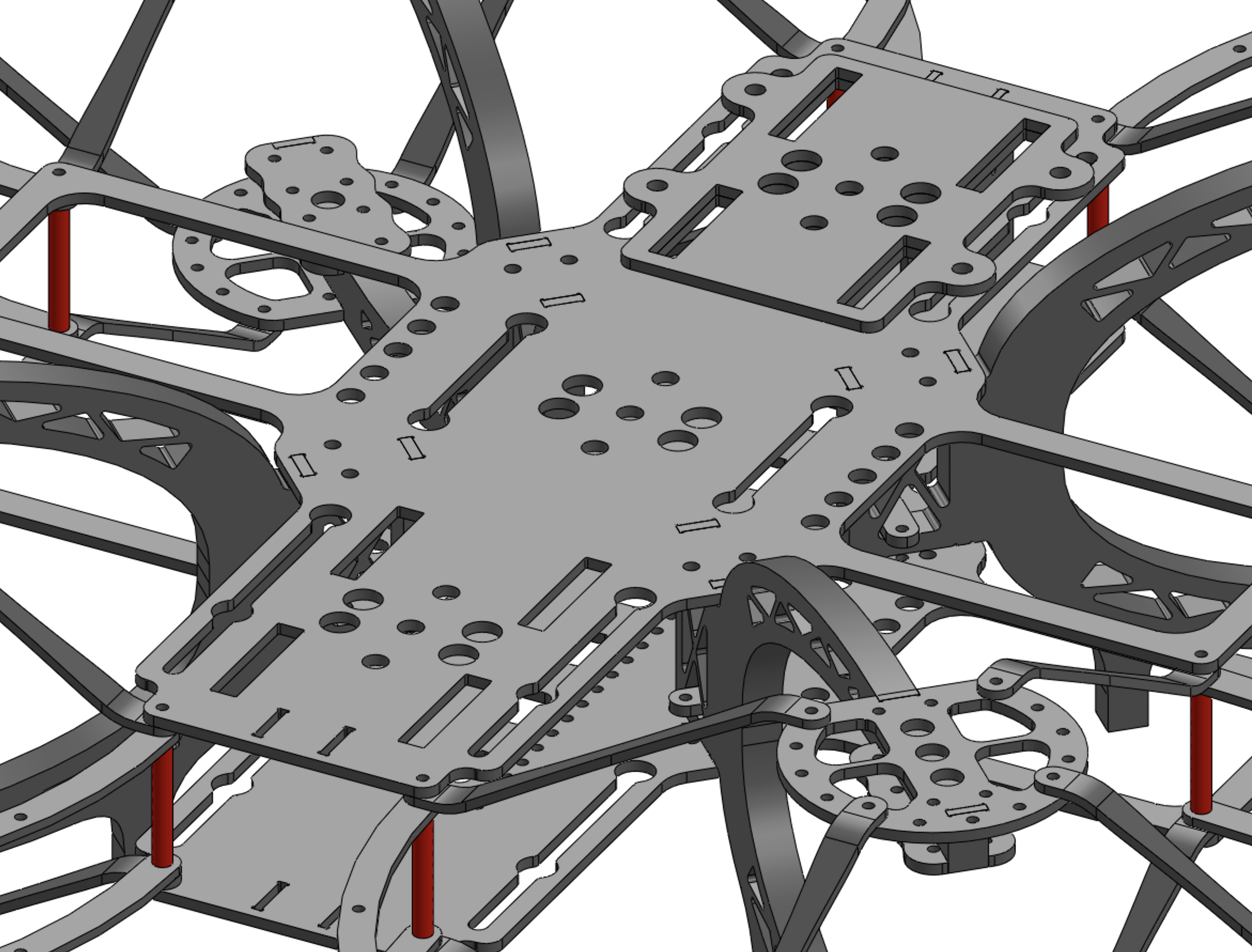
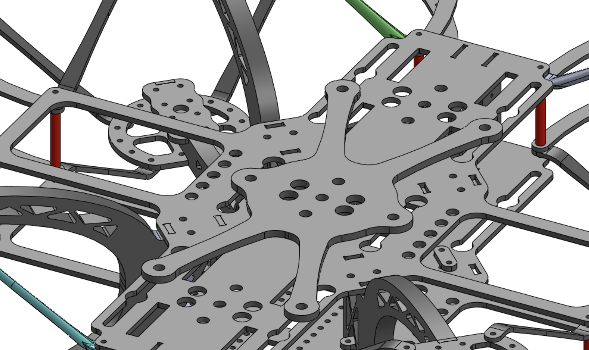
Next I started laying out the body. I kept it as symmetrical as I could, adding slots that double as QR mounting points and battery strap slots. Here it is with varying numbers of struts, as well as no propguards at all.

The top right version is what it would look like with no propguards. The arms are still braced in this configuration.
Next I added a cam plate that can hold a DAC mount as well as Tilta gimbal mount. The wider holes in the slots are where a locknut would slip through, and I spaced them at 50mm intervals to make cam plates easier to design.
If you don’t need to swap things around quickly the top plate is drilled to direct mount gimbals and DAC’s.
Then I drew another plate for center mounted gimbals. Both plates can go above or below the frame.
And here’s an option for hand catching.

The two vertical plates in the nose are fpv cam mounts.
And with that I was done. I’m pretty happy with how it came out. Those little arm holding tabs will make it easy to build, and once built you can pop it open without the arms falling off. And while it does have a lot of parts, it’s much simpler than other fully shielded frames I’ve seen. In its basic form it has just 36 pieces of carbon plus the minimum of 32 struts. You can make it as safe or as agile as you want. And it’s super modular. You can mount stuff anywhere, and balance it out by mounting batteries anywhere as well.
Time to order the carbon. I knew this would be a pricey frame, given the size of some of the pieces – the body plates and propguards eat up tons of carbon. I thought the struts would end up around 3 or 4 bucks each, after an initial investment in the molding to create the curved carbon sheets.
The factory sent over the invoice and boy was I wrong. The struts wound up being ten bucks each, or $320 at least per frame! And that’s just the struts! The frame would end up retailing for something like $1800, which is just insane. I had to find another way to make the struts.
I was concerned that airflow would make the struts vibrate and ‘whistle’, but I figured that 2.5mm carbon struts would be ok. But then I realized that if I got them injection molded I could draw them with a vertically oriented ovalized profile, which should make them less turbulent. I ordered the rest of the carbon parts and set about redesigning the strut.
1st Iteration
The carbon arrived and I was feeling pretty smug. Everything came together perfectly, and the embedded press nuts made assembly way simpler. I sent pics to Gab, and he responded “#firsttry”. Oh yeah, I thought, I’m good.

I printed up some PLA struts and they stiffened up the frame a ton.

The struts work mostly in tension instead of compression, so even these flimsy PLA struts work really well.
XNova was kind enough to send some 3215-700’s, and I threw them on, and got a nasty surprise…

That prop’s a little too close to the strut.
I had calculated the clearance based on the taller Brotherhobby motors, but with XNovas the prop tips got a little too close to the struts. Fortunately this could be fixed with just new arms. I increased the body stack height from 45 to 50mm, the propguard spacing from 35 to 40mm. I also moved the motors 3mm closer to each other, and ordered new arms. So much for #firsttry.
Next I got to work on an injection molded strut. This should’ve been relatively straightforward but it turned out to be quite the ordeal. It took several tries before I figured out the right way to think about its geometry. In hindsight it’s hard to understand why it would be complicated at all.
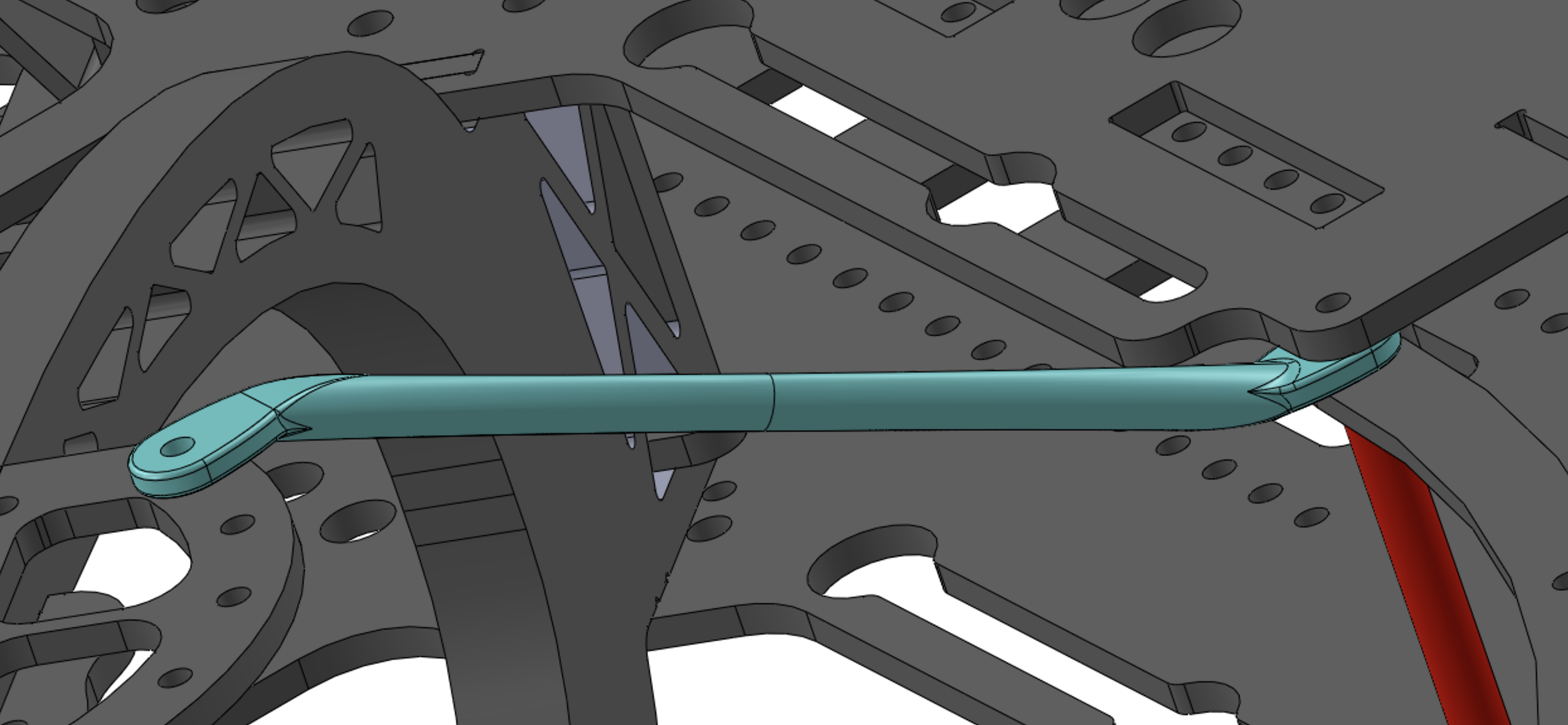
Looks like a straight extrusion but it actually narrows down in the middle.
I also drew up a printable version with a flat side. I figured it’d take a while to get the molded struts, so we could test in the meantime with cleaner printed struts. I printed them up and, to be honest, they felt so good they made me wonder if molded struts are even necessary.
